• Rss

SIL3 Pty Ltd

  • About SIL3 Pty Ltd
  • Contact Us
  • Consulting
    • Showcase
    • Safety Design Consulting
    • Embedded Firmware for Safety Applications
    • CPLD and FPGA Design
    • Printed Circuit Board Design
  • Technology
    • EWP Crush Protection
    • maxLMS
    • microLMS
    • LMS2
  • Safety Blog

Archive for category: SafeTool

You are here: Home » Safety Blog » SafeTool

Blog entries about our internal SafeTool – Functional Safety Management Tool

FMEDA Process – Component Entry

09 Aug 2015 / 0 Comments / in SafeTool/by Lachlan

The FMEDA (Failure Modes Effects and Diagnostics Analysis) is a critical systematic analysis process to determine the Safety Integrity Level (SIL) of a hardware design and is required by IEC 61508, IEC 62061, ISO 13849-1, and ISO 26262 to limit the probability of dangerous undetectable failures in hardware.

Safety Parameters

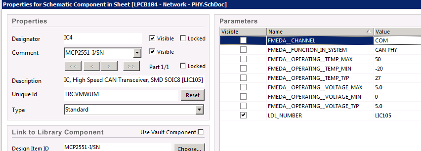
Each component in our component database (located on a SQL server) has a set of parameters which include data sheets, 3D models, safety parameters, stock control, purchasing information etc.

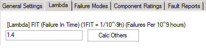
For each part that we add to the database we start off by setting the lambda value (FIT – Failures per 10^9hrs of operation). Typically these values are available from the manufacturer (often under NDA) or from various calculation tools or military handbooks.

lambda_entry

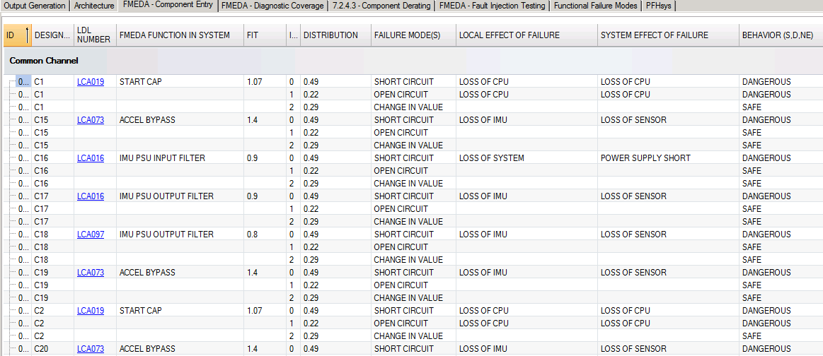
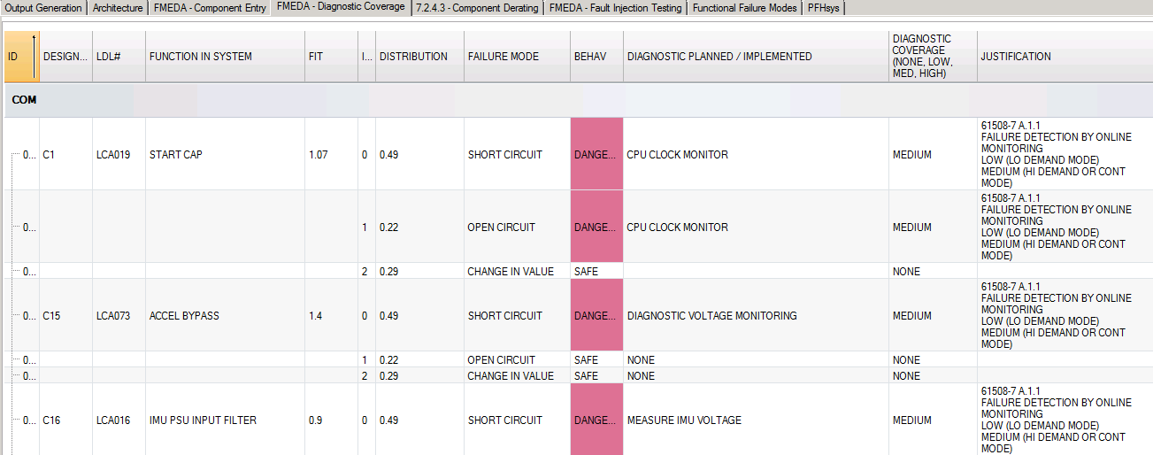
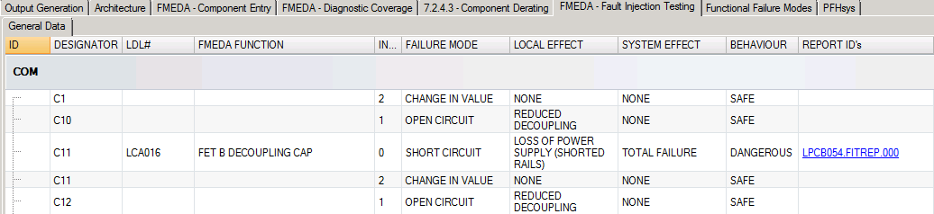
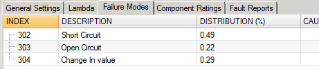
Next we enter in the failure modes. Failure modes are often derived from historical sources such as military handbooks. The failure mode distribution is important because it is used later on in the FMEDA process when we apply diagnostic tests to the hardware.

failure_mode_entry

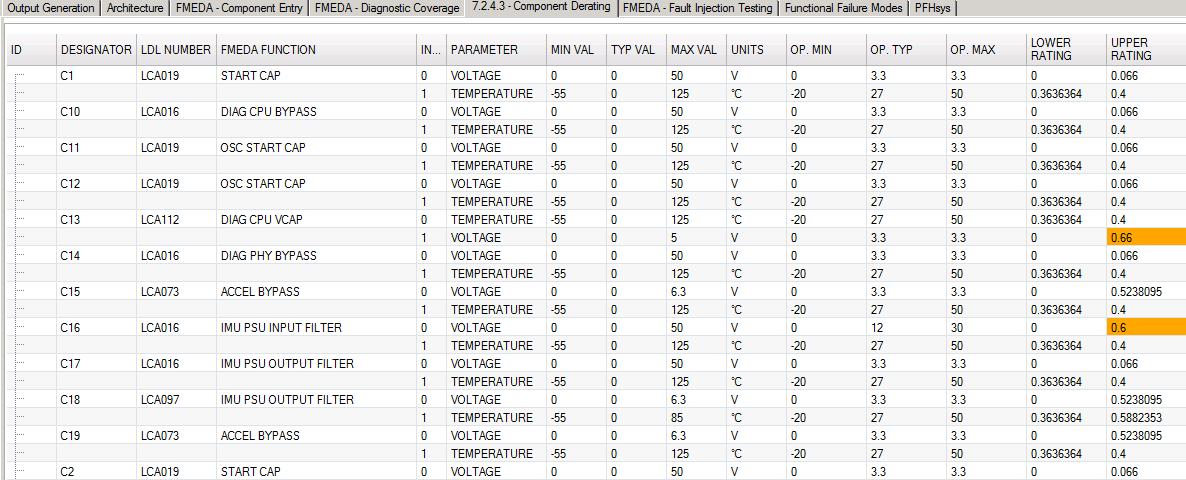
Finally we enter the component ratings. Ratings are parameters like limiting voltages or temperatures, currents and frequencies. The component ratings are used to determine sufficient design margin later on in the FMEDA process.

component_ratings

In the next entry we will discuss configuring components in Altium Designer for use with the SafeTool FMEDA process.

Do you need help with your FMEDA process? Contact Us

FMEDA Process – Schematic Capture

09 Aug 2015 / 0 Comments / in SafeTool/by Lachlan

Each hardware component that we use on a PCB, not only has a Parts Database entry but also has a schematic symbol in Altium Designer. Within the symbol we have added links to enable the rapid creation of the necessary data for the FMEDA process.

Schematic Symbols

Each symbol contains additional information for the SafeTool application. This information includes:

  • The channel (for multi channel MooN architectures)
  • The function of the component in the system
  • Its operating conditions when used in the system, including min, max and typical values.

schematic_01

schematic_02

This process allows the designer and design review team to quickly identify each component in the system, its function and its operating conditions.


Do you need help with your FMEDA process? Contact Us


SafeTool – FMEDA Configuration

09 Aug 2015 / 0 Comments / in SafeTool/by Lachlan

To setup the FMEDA process in SafeTool a few elements must be manually entered:

  • The Altium Designer PCB Project
  • The type of hardware architecture:
    • Type A: Components with well known failure modes
    • Type B: Complex components / silicon
  • The number of channels in the system
  • A justification for each choice
  • The Demand Mode

safetool_fmeda_architecture

The information entered into SafeTool is used at the final step in determining the SIL level for the current design.

SafeTool – FMEDA Component Entry

09 Aug 2015 / 0 Comments / in SafeTool/by Lachlan

Once the FMEDA has been configured we need to then systematically detail the failures for each component and their failure modes to determine if the particular failure is safe or dangerous in our system.

This process is considered PRIOR to any diagnostic functions.

For each component and its failure mode:

  • Determine the local effect of the failure
  • Determine the system effect of the failure
  • Determine if the failure is safe or dangerous prior to diagnostics
  • Apply any justifications

fmeda_component_entry

As the process is a systematic process each failure mode must be determined prior to proceeding.

SafeTool – FMEDA Diagnostic Coverage

09 Aug 2015 / 0 Comments / in SafeTool/by Lachlan

The next step in the FMEDA process is to apply any diagnostic coverage to each failure mode of each component.

fmeda_failure_modes

The failure mode entry consists of:

  • The implemented diagnostic
  • The effect of the diagnostic (high, medium, low)
  • The justification per IEC61508 tables.

SafeTool – FMEDA Fault Injection Testing

09 Aug 2015 / 0 Comments / in SafeTool/by Lachlan

Fault Injection Testing is the mechanism that is used to confirm that the FMEDA failure effects and diagnostics determination is correct.

Fault Injection Testing is a systematic process that is performed on every component and every failure mode. SafeTool permits systematic Fault Injection Testing and test reports to be created.

fault_testing

Each test report allows a large amount of information to be captured for each Fault Injection Test including:

  • Project, Date, Time, Test Engineer
  • Intent of test
  • Test Conditions
  • Expected Reaction
  • Actual Reaction
  • Reaction Time and Comments
  • Pictures of Setup and Reaction

fault_test_report

SafeTool – FMEDA Component Ratings

09 Aug 2015 / 0 Comments / in SafeTool/by Lachlan

For each component we have a series of minimum and maximum ratings as specified in the schematic capture phase.

SafeTool details each of the ratings and determines the upper and lower percentage for each rating item.

Items that are greater than 60% of their tolerance are highlighted in orange, and items that are around or greater than 100% of their tolerance is highlighted in red allowing further testing or component changes.

fmeda_component_ratings

SafeTool – FMEDA Output Generation

09 Aug 2015 / 0 Comments / in SafeTool/by Lachlan

The final step in the FMEDA process is the output generation.

Output Generation Covers:

  • Determination of SIL and Lambda values
  • Generation of the FMEDA spreadsheet
  • Generation of PDF test reports to add to the projects Safety Case.

safetool_fmeda_output


Recent Posts

  • FMEDA Process – Component Entry
  • FMEDA Process – Schematic Capture
  • SafeTool – FMEDA Configuration
  • SafeTool – FMEDA Component Entry
  • SafeTool – FMEDA Diagnostic Coverage

Archives

  • August 2015

Categories

  • SafeTool

© Copyright - SIL3 Pty Ltd - Terms and Conditions - Replete e-Commerce Theme by Kriesi
  • About SIL3 Pty Ltd
  • Contact Us
  • Consulting
  • Technology
  • Safety Blog