PCB Design & Prototyping

From a systems engineering model to production hardware — SIL3 has designed ~1300 PCBs across aerospace, industrial, radio, motor drive, power conversion, and biomedical applications. We offer in-house prototyping, full hardware lifecycle development, schematic and PCB capture in Altium Designer as well as 3D modelling. Our workflow includes built-in support for IEC 61508, DO-254, IEC 61709 and others.

~1300

PCB Designs Completed

20+

Years PCB Design Experience

50+

Processor Architectures
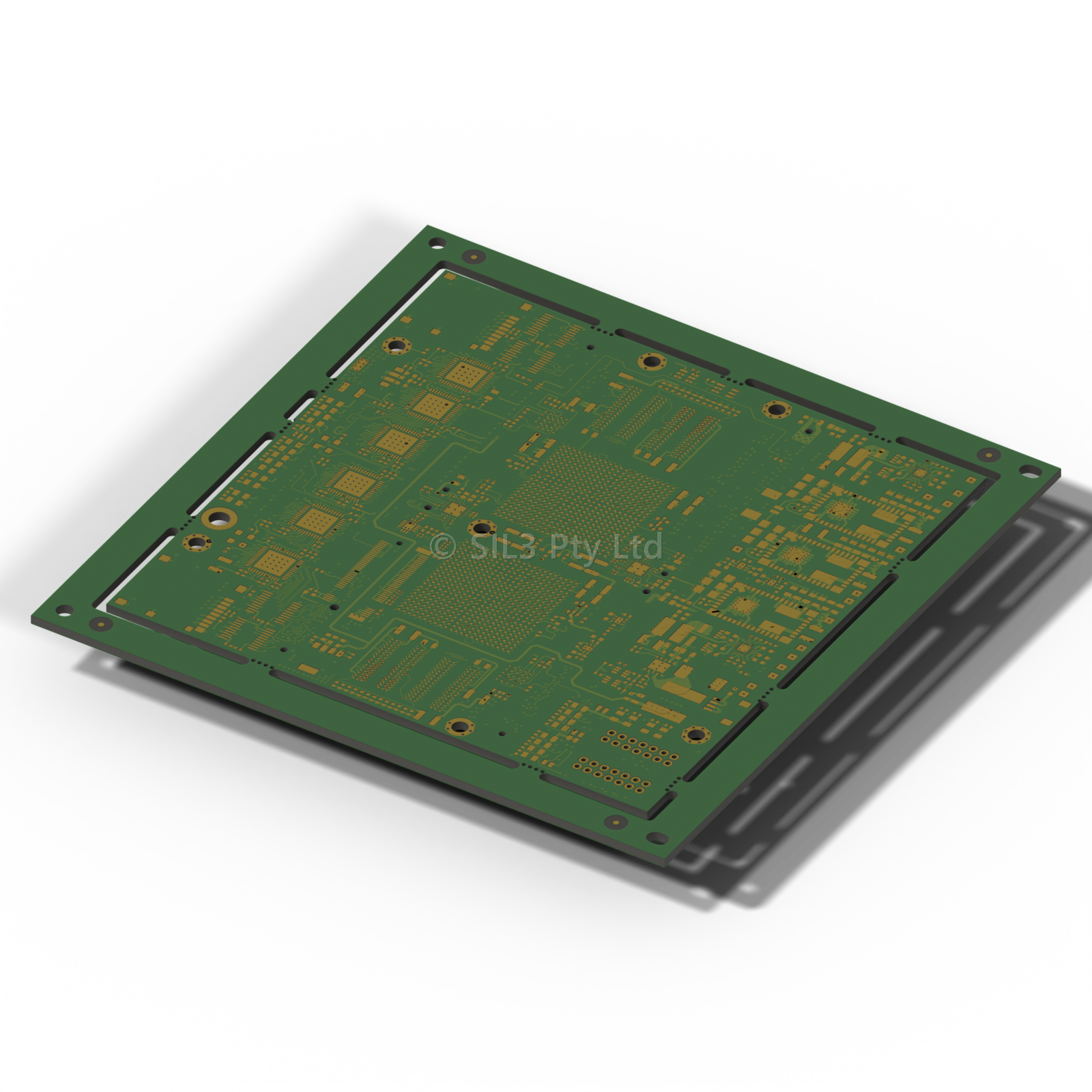
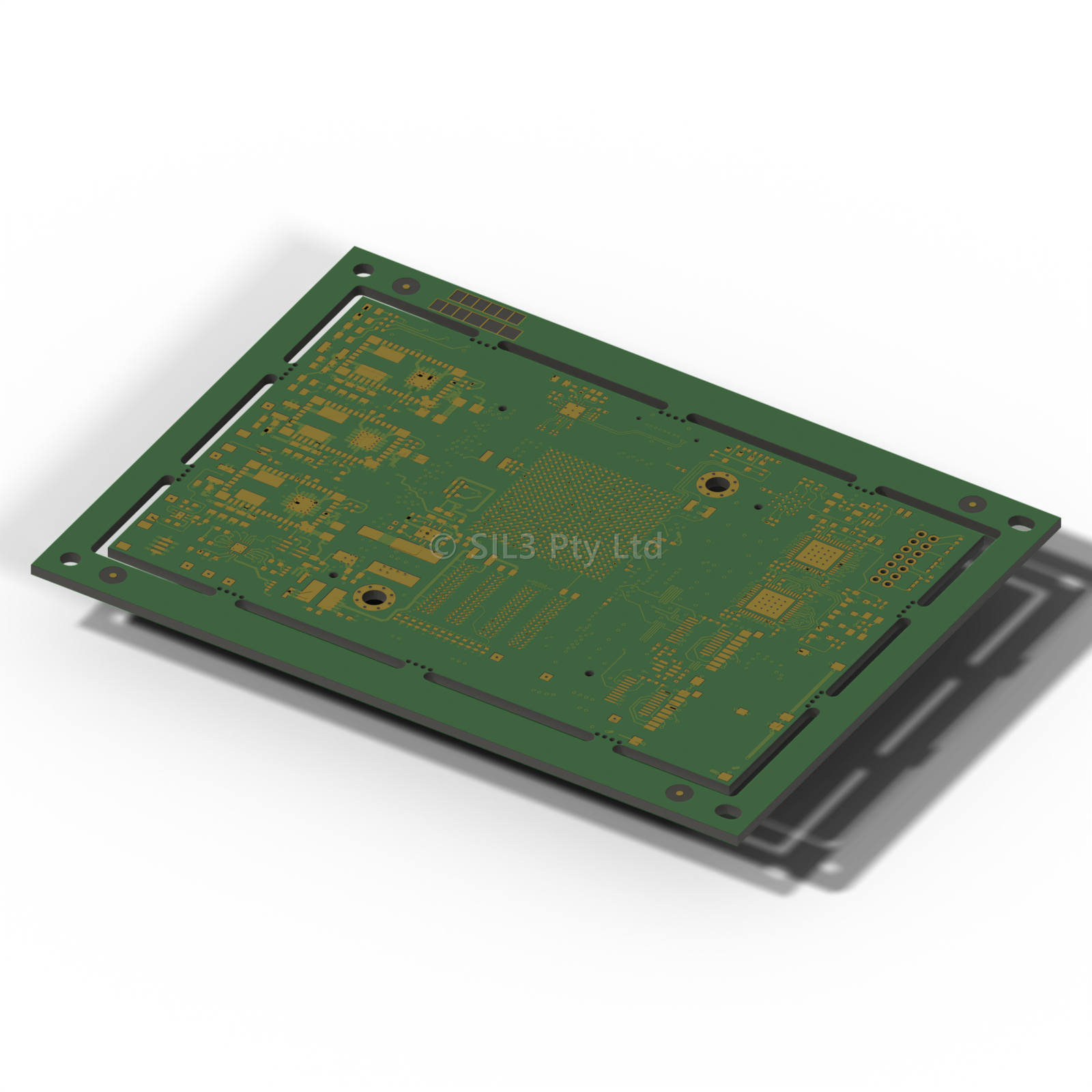
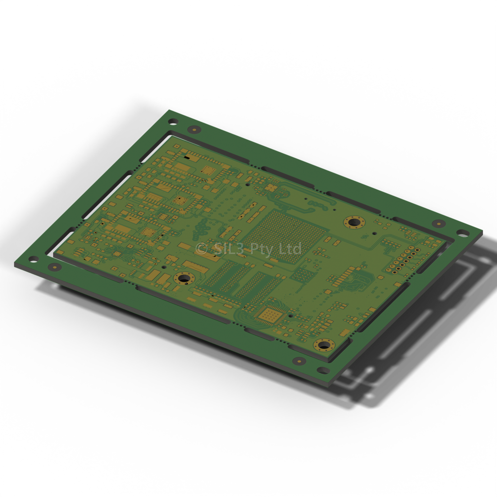
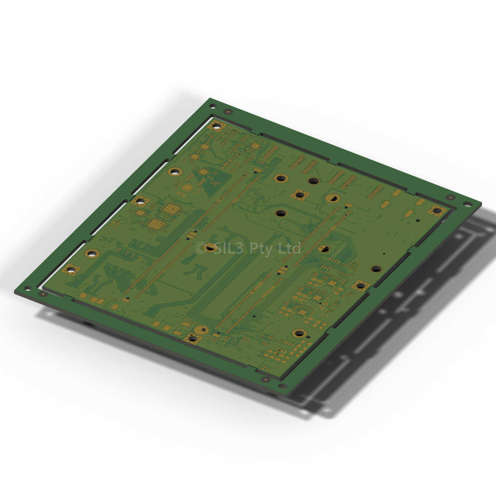
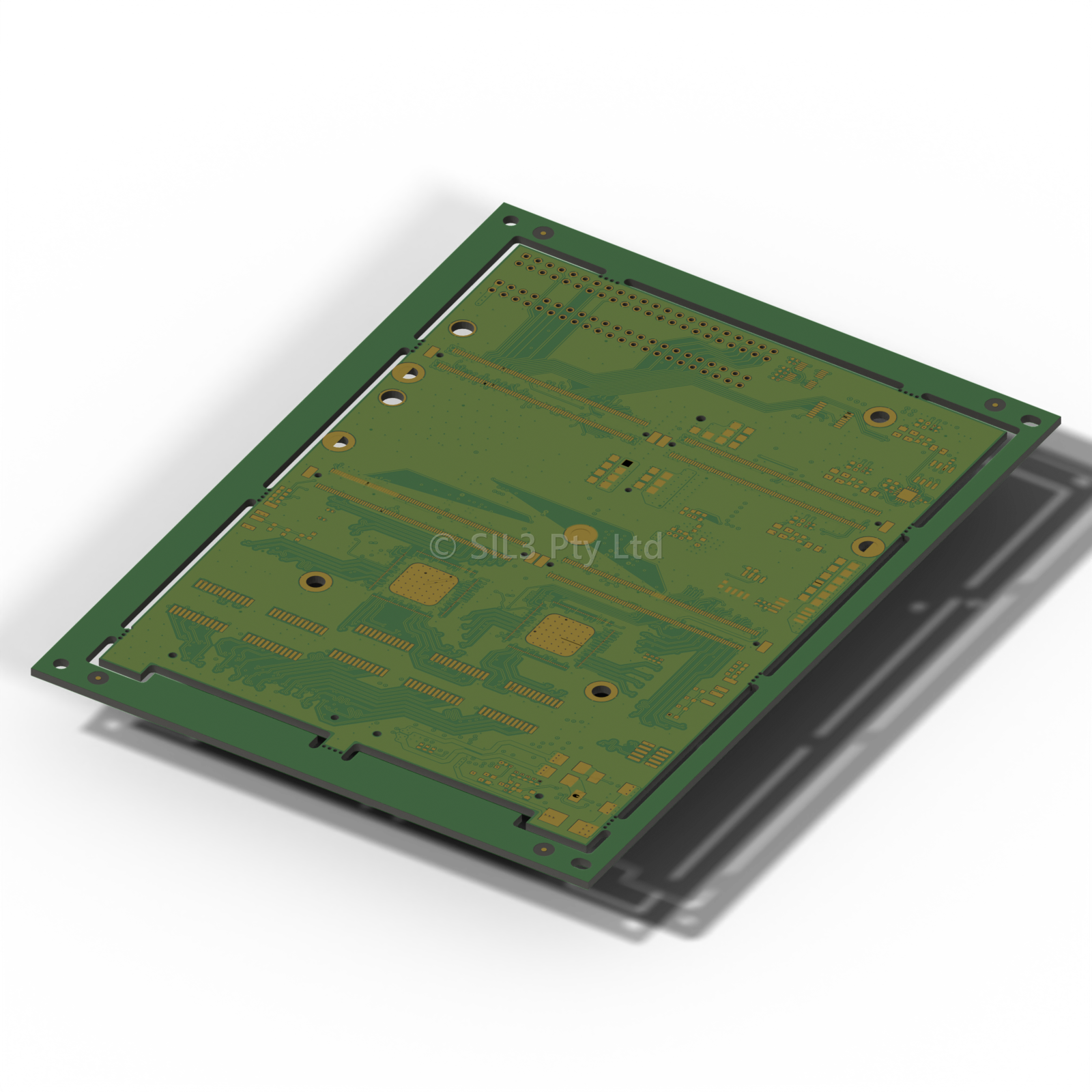
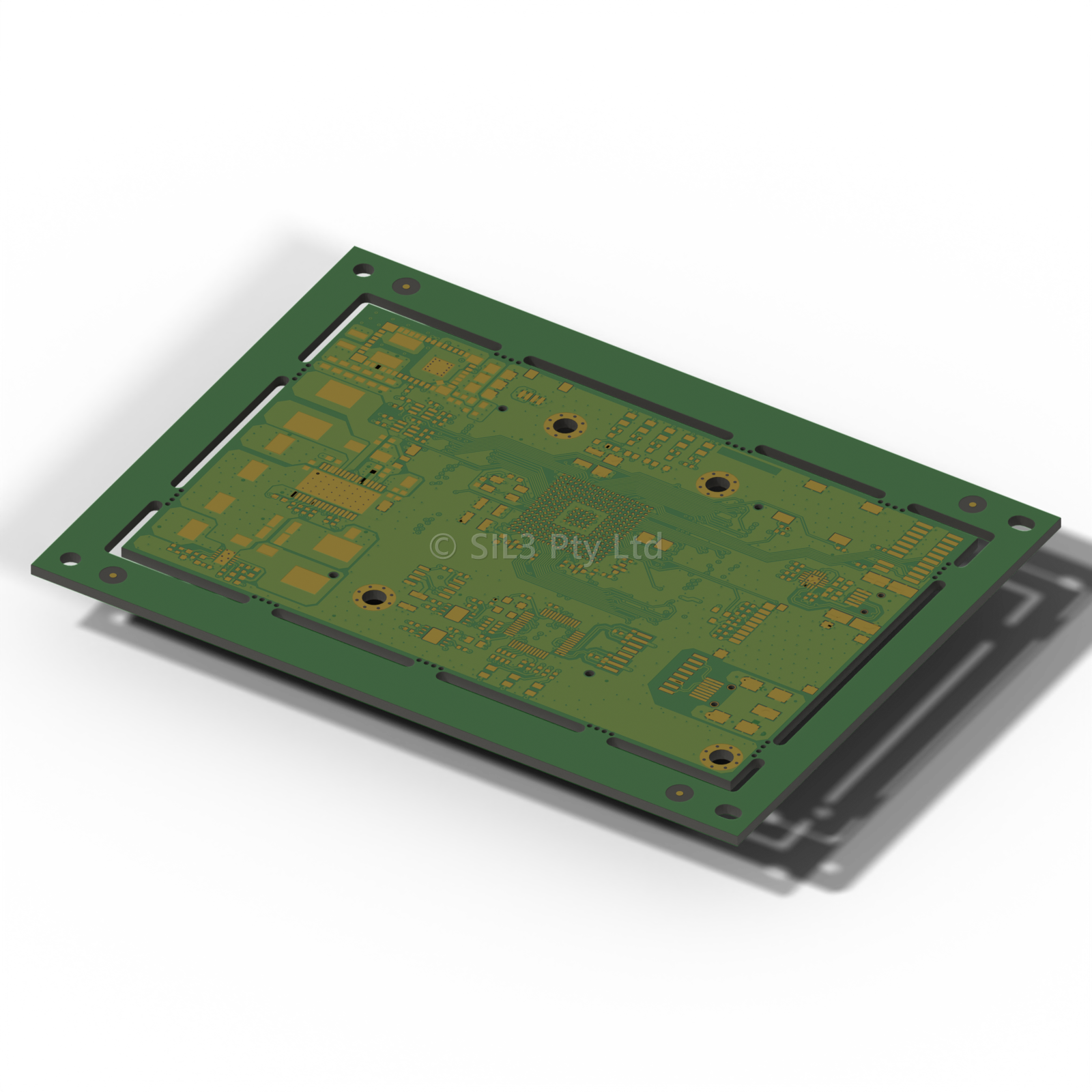
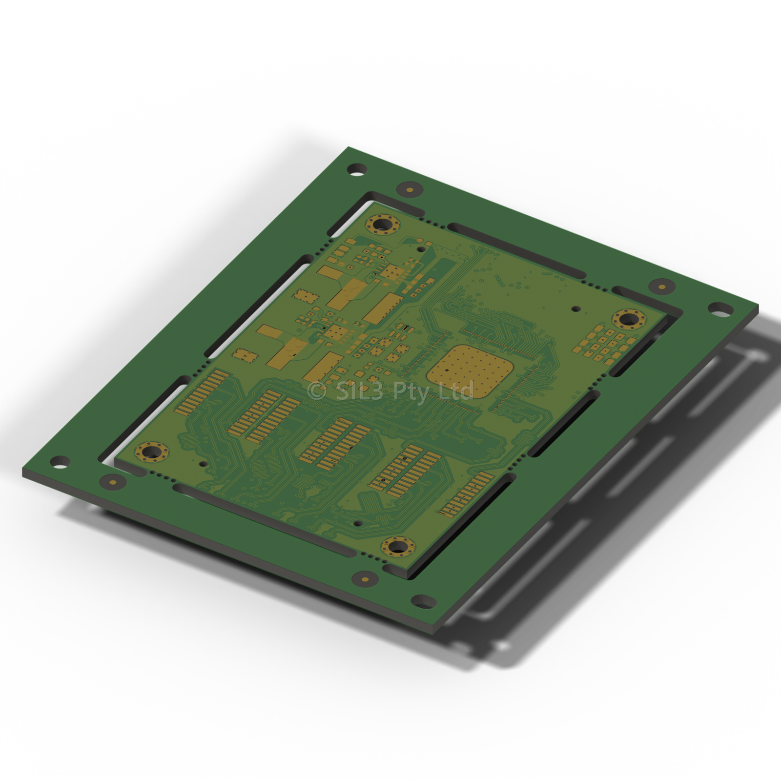
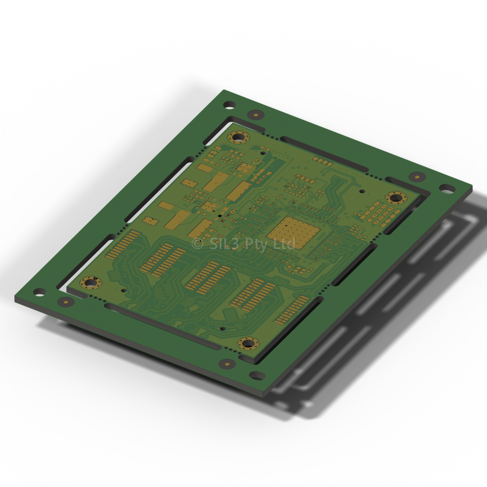
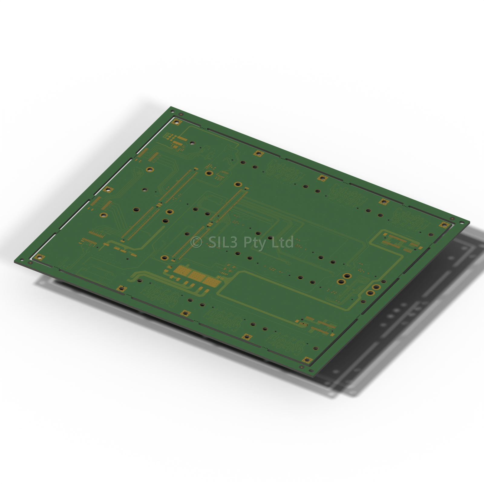
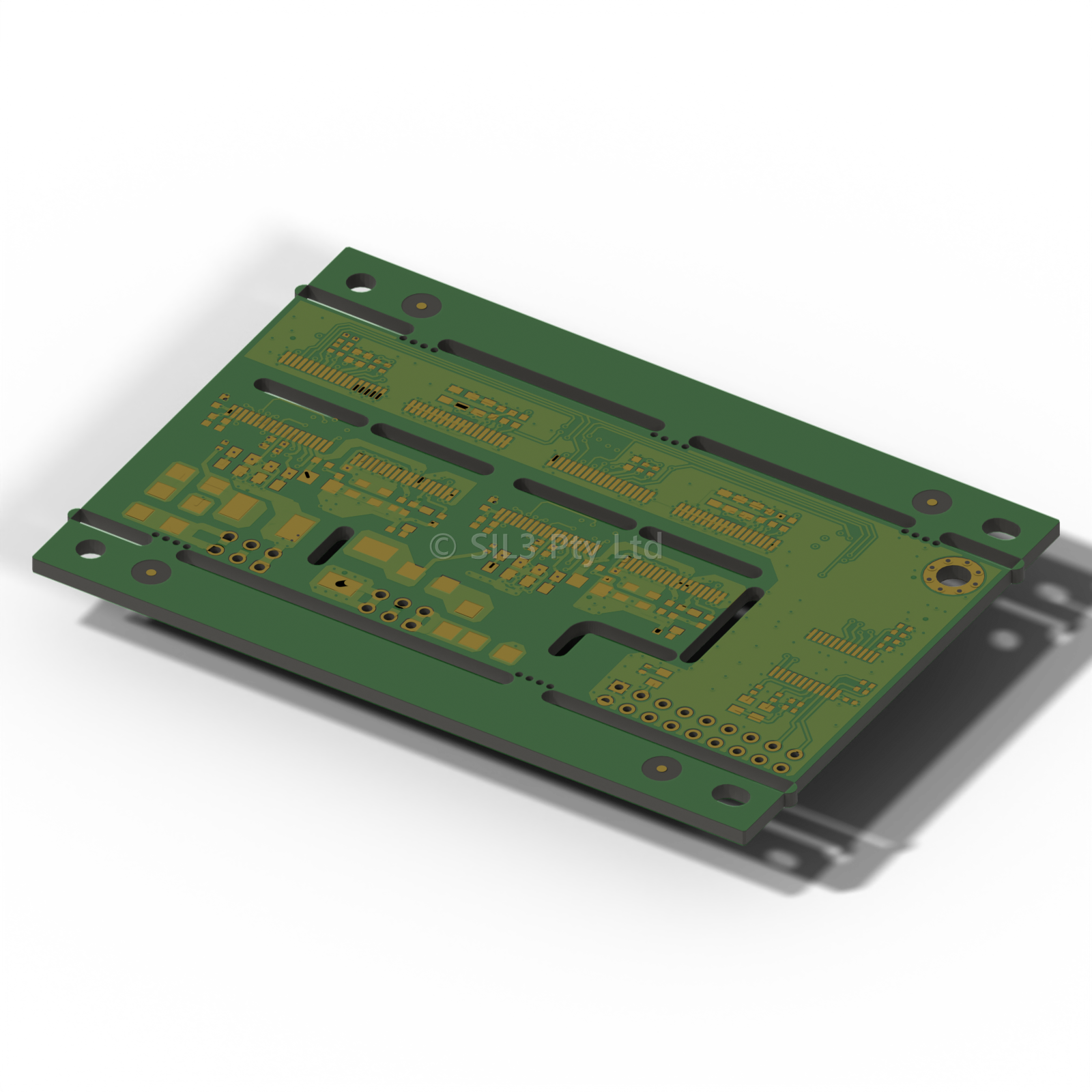
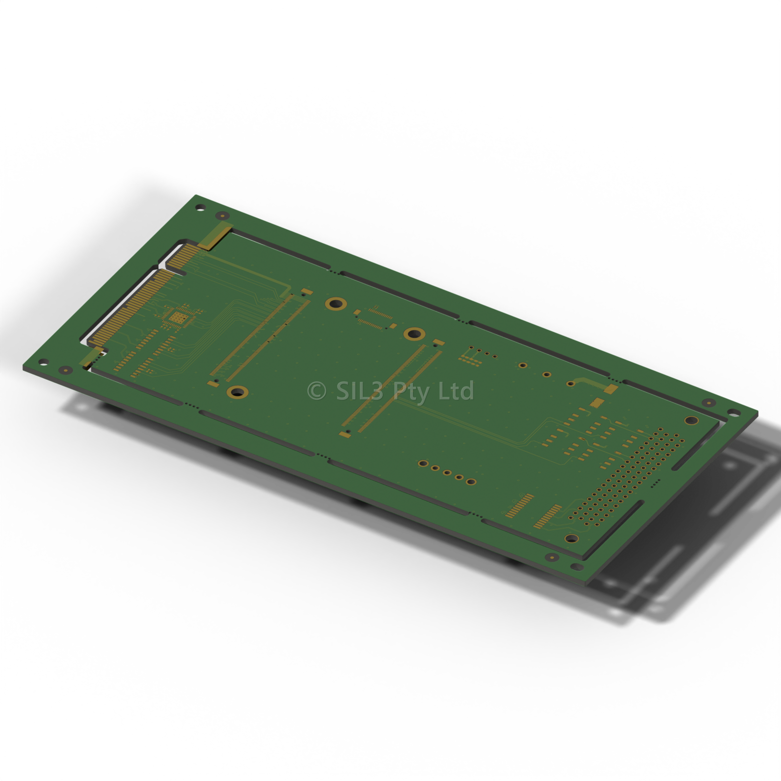
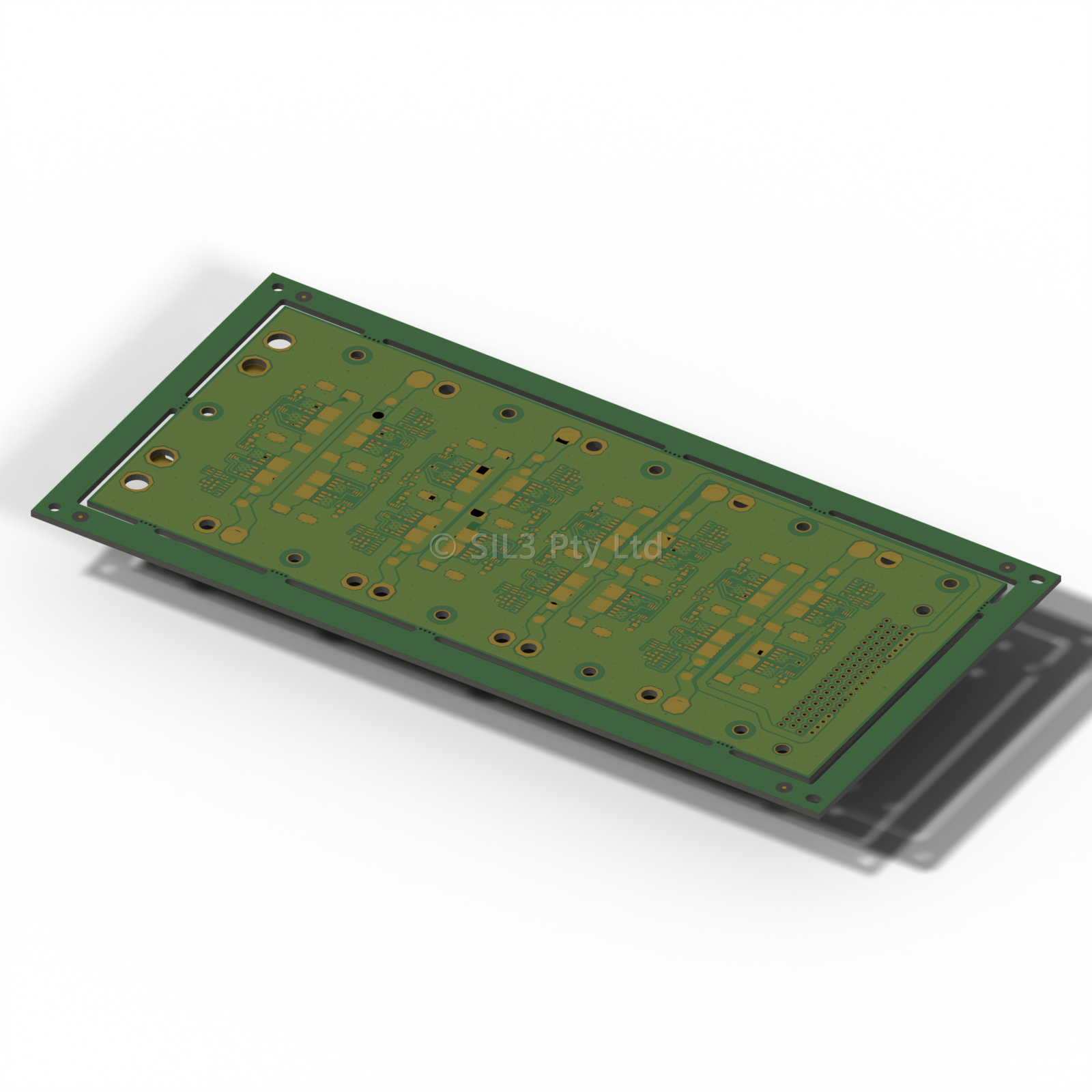
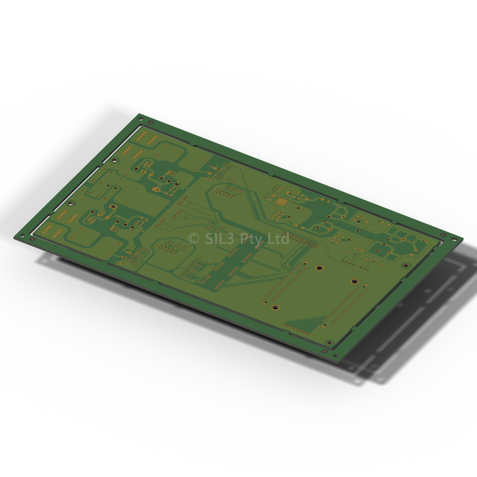
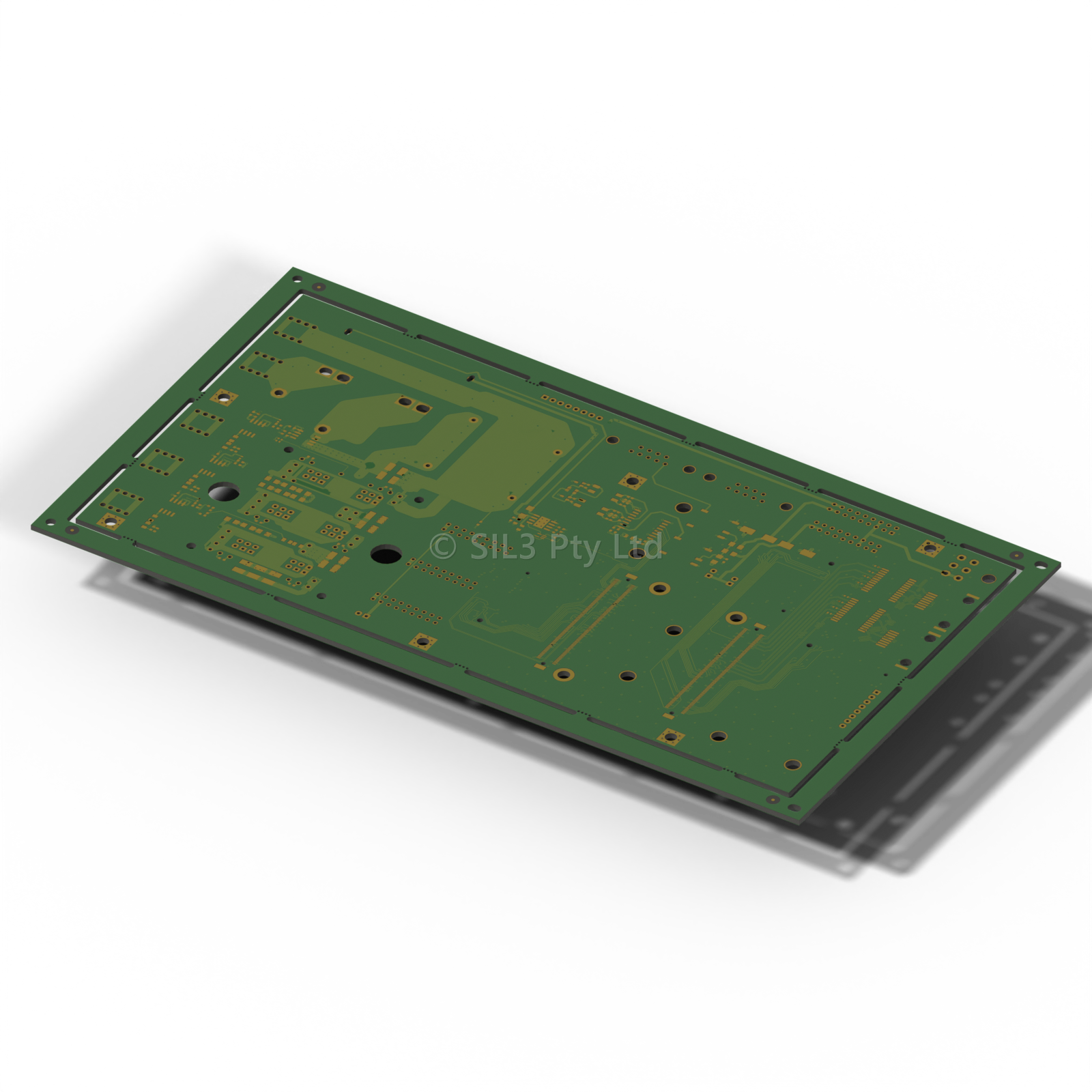
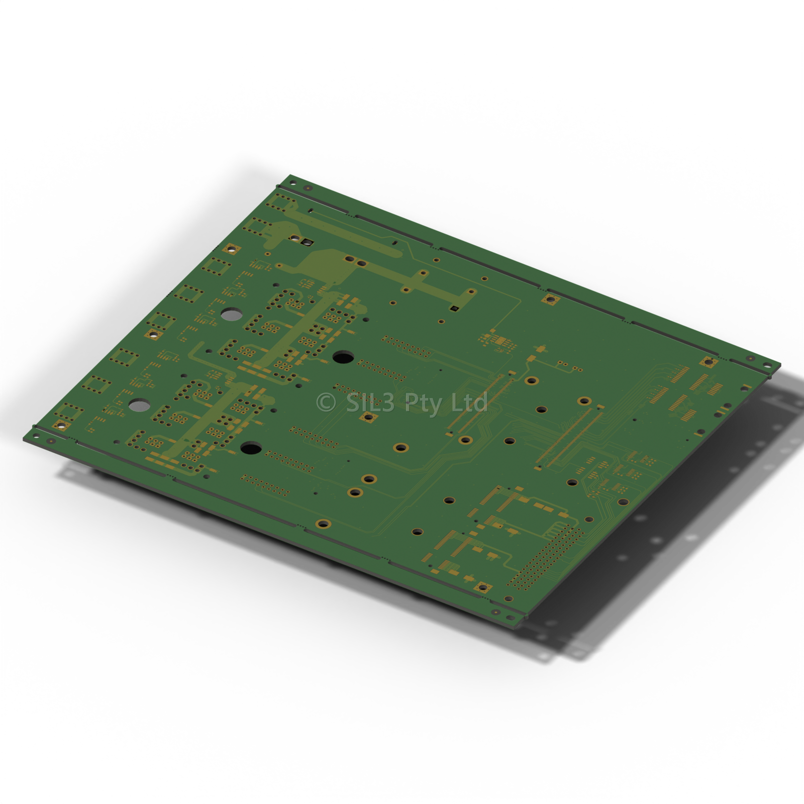
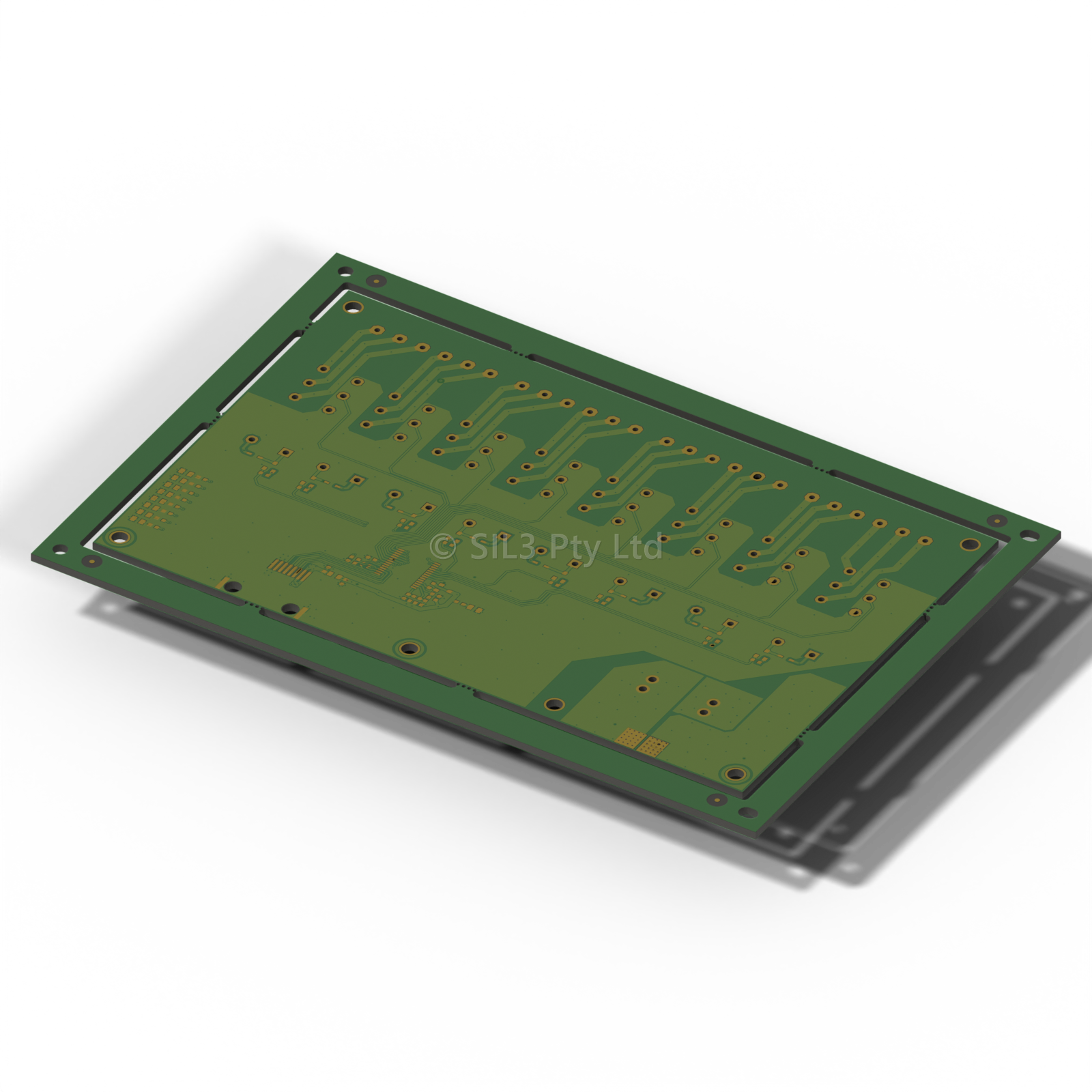
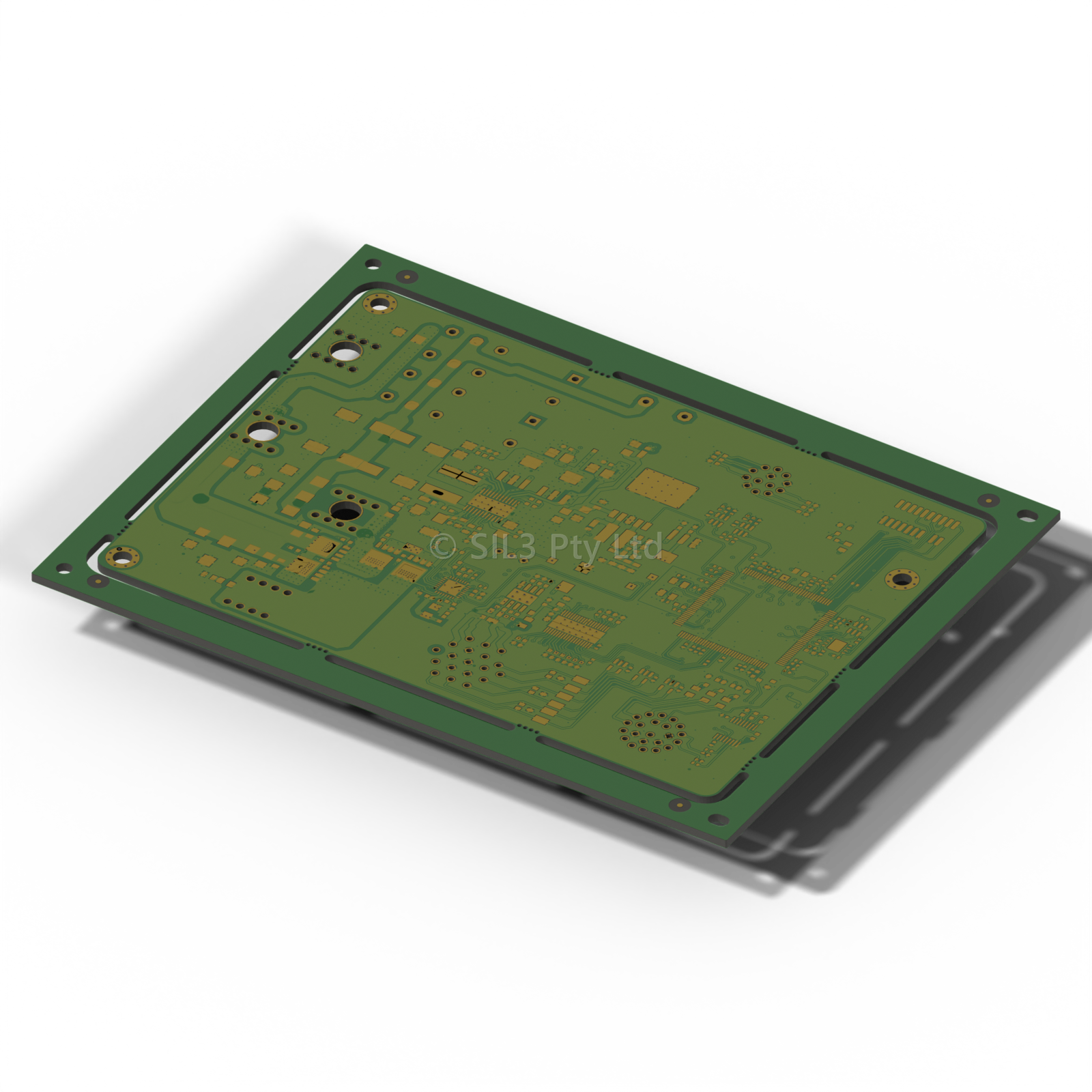
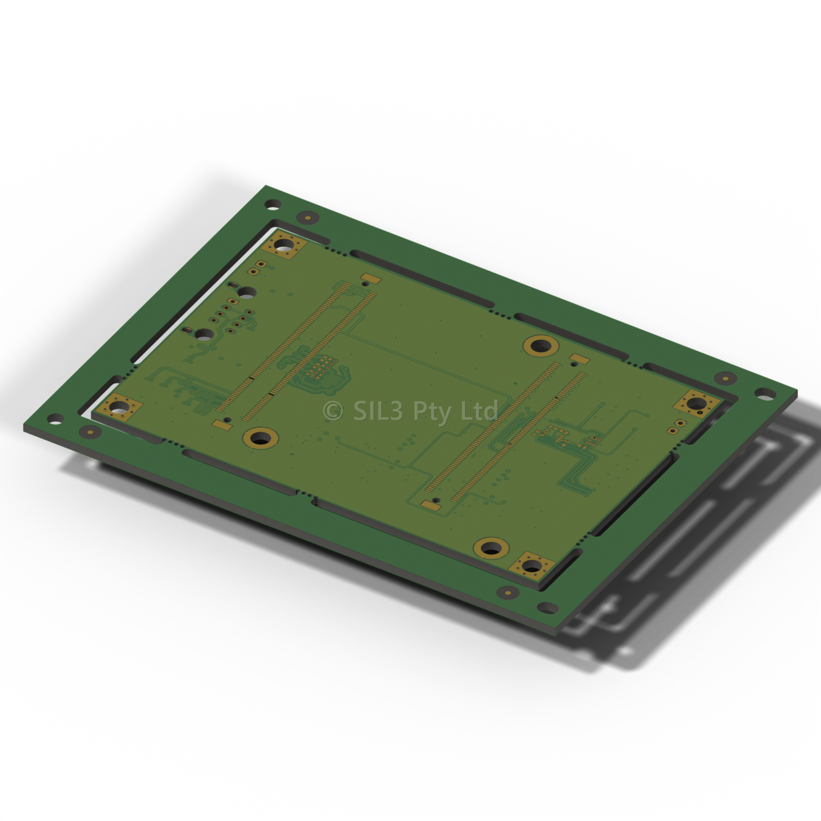
Full-Lifecycle PCB Engineering

SIL3 designs electronics across the full hardware development lifecycle — from customer requirements, system engineering model, through schematic, layout, FMEDA, prototyping, and release. Every design is captured in Altium Designer with structured library management, 3D modelling, and manufacturing documentation. Safety analysis can be performed to relevant standards such as IEC 61508 and DO-254.

PCB Design Capability

SIL3 designs hardware across a broad range of application domains. The same safety process and Altium toolchain applies regardless of application — only the requirements change.

Application Domains
Safety Hardware
IEC 61508 SIL 1–3 rated E/E/PE systems
Flight Hardware
Avionics, flight control, data logging, DO-254 capable processes
Motor Drive Systems
Inverter power stages, Silicon Carbide (SiC) systems.
Sensor Interfaces
ADC front-ends, signal conditioning, isolated I/O
Communications Modules
CAN, Ethernet, RS-485, RF, fibre-optic interfaces
Battery Management
BMS, cell monitoring, charge balancing, protection circuits
Industrial I/O
Ruggedised digital I/O, 4-20mA
Display & HMI
MIPI DSI / LVDS display boards, touch interfaces
Power Conversion
DC/DC converters, LDO regulators, isolated PSUs, PDN design
Biomedical Systems
Patient-connected hardware, low-noise analogue front-ends, IEC 60601

Altium Designer Workflow

Every SIL3 PCB is designed in Altium Designer with a consistent process: structured requirements, library-managed components, DFM-verified layout, and full manufacturing documentation output.

Systems Engineering & Requirements Capture
Every PCB design begins with formal requirements capture in SIL3’s in-house ARP Tool. Customer and system requirements are decomposed to hardware requirements, allocated to circuit-level design elements, and fully traced throughout the design lifecycle.
Altium Designer
Industry-standard schematic and PCB layout. Unified library management, DRC, DFM rules, multi-board project support, and 3D modelling. All designs archived with version-controlled project files.
Component Library Management
Centralised library with SIL3 part numbers linked to our Database. Every symbol, footprint, and 3D model is validated before use. Schematic parameters carry FMEDA and operating point data directly for tool analysis.
3D Modelling & DFM
Mechanical checks and further analysis are usually performed in Autodesk Inventor / Nastran. Design-for-manufacture rules: clearance, annular ring, copper weight, soldermask expansion, panelisation, and impedance control are handled natively in Altium.
PCB Qualification
The final phase of the hardware V-model. Structured qualification test procedure covering power sequencing, rail verification, clock validation, and oscilloscope characterisation of key nets. Further mechanical and environmental stress testing can be performed. Qualification evidence is captured against hardware requirements in ARPTool before release.

Prototyping & Small Production Runs

SIL3 operates an in-house surface-mount pick-and-place robot, enabling rapid prototype assembly for 0201 and larger components. Short production runs can be managed in-house, with typical quantities from 2 to 10 units.

In-House Prototyping Capability
SMD Pick-and-Place
PNP Machine Gen3 — in-house robot, 0402 and above
Small Production Runs
Low-volume assembly for prototype and pre-production
PCB Bring-Up
Power rails, clocks, comms verified before firmware load
Integration Testing
Hardware + firmware integration against structured test specs
Test Fixtures
In-house bed-of-nails and functional test fixtures for hardware validation
CNC Machined Enclosures
Prototype enclosures CNC machined in-house for early-stage hardware integration
EMC Pre-Compliance
In-house pre-scan before formal EMC laboratory submission

Functional Safety

Safety analysis is not a post-design activity at SIL3 — it is embedded in the design process. FMEDA data is captured at component level in the schematic, and hardware qualification follows IEC 61508 Part 2 and DO-254 hardware lifecycle processes. Learn more about our functional safety methodology.

FMEDA at Schematic Level
Failure Mode Effects and Diagnostic Analysis is performed directly from the Altium schematic. Component parameters carry FMEDA data — failure rates (FIT), diagnostic coverage, and safety function classification — so the safety case is always synchronised with the circuit design.
Component Stress Derating
Every component is verified against manufacturer ratings for voltage, current, temperature, and power dissipation. Derating margins follow IEC 61709 guidelines and are documented as part of the hardware safety case submitted for certification.
DO-254 Hardware Lifecycle
Hardware design assurance following DO-254 guidelines: hardware requirements, conceptual design, detailed design, implementation, production transition, and acceptance test. All artefacts are traced in ARPTool with full revision history.
IEC 61508 Hardware Lifecycle
Hardware safety lifecycle per IEC 61508 Part 2: hazard and risk analysis, hardware requirements specification, design and implementation, verification, and validation. SIL 1–3 compliant architectures with full fault tolerance and hardware fault metric documentation.

Processor & FPGA Platform Support

SIL3 has designed board support hardware for over 50 processor and FPGA architectures. Board support includes power supply, clock tree, debug strategies, boot configuration, and peripheral interfaces tailored to each device. We have an extensive design-reuse system capturing many of our frequently used CPUs, FPGAs and power supplies.

ARM Application Processors & SoCs
Xilinx Zynq-7000
Dual Cortex-A9 + FPGA, XC7Z010 to XC7Z045
Xilinx Zynq UltraScale+
Quad Cortex-A53 + FPGA, XCZU2EG to XCZU15EG
TI TDA4VL / TDA4AL
C7x DSP + Cortex-R5F, ISO 26262 ASIL-D
TI AM67A
Cortex-A53 + MMA, edge AI vision
TI AM263PX
Quad Cortex-R5F lockstep, IEC 61508 SIL-3
TI AM3358
Single Cortex-A8, Linux/RTOS BeagleBone industrial
Safety MCUs
TI TMS570 / RM57
Dual Cortex-R4F lockstep, ISO 26262 / IEC 61508 SIL-3
TI TM4C1294NCPDT
Cortex-M4F, 120 MHz, Ethernet MAC, FreeRTOS
TI MSPM0L1306
Cortex-M0+, ultra-low power, IEC 60730 Class B
STM32 Series
STM32F4, STM32H7, STM32L4 board support
FPGAs
Xilinx 7-Series
Artix-7, Kintex-7, Spartan-6 standalone boards
Xilinx UltraScale+
High-bandwidth FPGA, PCIe, multi-GT transceiver
Intel / Altera
Cyclone IV / V board support designs
Lattice ECP5
Low-power FPGA applications
Microcontrollers
TI CC1310 / CC1352
Sub-GHz and multi-band RF SoC
TI CC2650
Bluetooth Low Energy IoT edge nodes
TI MSP430
Ultra-low power MSP430F/G series
Microchip PIC / dsPIC
PIC18, PIC32, dsPIC33 motor control

SIL3 maintains board support designs for 50+ processor architectures.

Standards & Compliance

SIL3 hardware designs integrate safety analysis, quality management, and design assurance into a single traceable process.

IEC 61508 SIL 1–3
Hardware safety lifecycle for E/E/PE systems. Fault tolerance architecture, FMEDA, hardware fault metrics (SFF, DC, HFT), systematic capability, and proof test planning. Applicable to industrial, energy, and machinery applications.
DO-254
Airborne electronic hardware design assurance. Hardware requirements, conceptual and detailed design, implementation, validation, and acceptance test artefacts — all managed in ARPTool with full traceability from system-level requirements.
AS9100D / ISO 9001
Quality Management System. Controlled design records, change management, supplier approval, first-article inspection, and configuration management procedures documented under the SIL3 QMS.
IEC 61709
Component reliability data and stress models for electronic components. SIL3 applies IEC 61709 failure rate models and reference conditions during component stress derating, directly supporting hardware fault metric calculations required under IEC 61508.
IEC 60730
Automatic electrical controls standard. Hardware designs targeting IEC 60730 Class B and Class C compliance include the required self-test, anomaly detection, and safe-state circuitry verified against the standard’s hardware requirements.

Ready to Design Your Next PCB?

Tell us about your application, platform, and safety requirements. We can scope a fixed-price design engagement or ongoing PCB engineering support.